Pneumatic despatch (or pneumatic dispatch) is the name given to Victorian PCPs using large diameter pipelines. These were generally more than 1 foot in diameter. The systems were beset by inadequacies in the technology, and experienced a mixture of political problems and bad timing. Unlike telegram conveyors, pneumatic despatch systems failed on almost every criteria set for them. In spite of this, they engendered a passion in those that promoted them.
London Pneumatic Despatch Company
The growth of telegram conveyors aroused the interest of the British Post Office in London. They commissioned two engineers (Gregory and Cowper) to investigate the possibility of a pneumatic tube based system between the General Post Office and a point on the corner of Little Queen Street and Holborn - to be the site of the West District Central Post Office. The engineers reported in 1855 and 1856 that such an idea was possible, (especially if 15" diameter used), but at significant cost. The Post Office dropped the idea.
In 1859 Thomas Webster Rammell and Latimer Clark combined Medhurst's ideas with knowledge of the Post Office's interest in PCP, to develop the London Pneumatic Despatch [1]. Rammell had previously proposed the development of an elevated street railway using two-carriage trains powered by atmospheric railway technology: the victorian equivalent of modern automated people mover systems [2]. They now proposed the development of an underground tube network within central London "for the more speedy and convenient circulation of despatches and parcels" [3]. It seems the engineers had aspirations for the system to eventually transport all kinds of general freight, and passengers. The network would link the main railway termini to post offices and marketplaces. Capsules would be powered by compressed air in one direction, atmospheric pressure in the other, with the capsule acting as a piston and adapted it to work with a stationary steam engine, a large reversible fan, and very low air pressure or vacuum [1]. The London Pneumatic Despatch Company (also sometime referred to as the London Pneumatic Dispatch Company) was formed on 30th June 1859 [3], and its Act of Parliament empowering the Company to open the streets and lay down tubes received the Royal Assent on 13th August 1859.

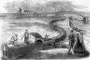
Pneumatic Despatch Company's prototype system at Battersea Fields, London, 1861 (Source: Beach).
The company initially raised £25,000 in order to test the technology and construct a pilot route. Early experiments were conducted at the Soho works of Boulton and Watt in Birmingham [4]. The first full-scale trial was on land owned by Vauxhall Waterworks and the London Brighton and South Coast Railway at Battersea, to the south-west of central London, during the summer of 1861. A single tube 30 x 33 inches ([5] quotes 2'9"x2'5" diameter) and 452 yards long, with curves up to 300 ft radius and gradients up to 1 in 22 was installed on the surface. 24 inch gauge track was cast inside the tube, upon which capsules fitted with vulcanised rubber flaps to make air seal ran. Power was provided by a 30 horse-power engine with 21 foot diameter fan. Single capsules weighed up to 3 tons, and achieved speeds up to 40 mph at pressures of 1 to 6 oz/sq in [5/1].
A permanent line was constructed between the Euston station of the London and North Western Railway (beneath platform one), and the North West District Post Office in Eversholt Street (1/3 mile), using a 30 inch diameter tube and similar technology to that tested at Battersea. The line was tested from 15th January 1863, and put into operation on 20th February 1863 [1] ([6] states 1862). A single capsule, conveying up to 35 bags of mail could make the short journey between terminals in one minute, twice the speed of mailcarts. 13 journeys were operated each day, with a daily operating cost of £1 4s 5d. The Post Office were charged a nominal fee for use of the service, presumably to encourage them to accept the technology. Vance [6] comments that the system had a much higher capacity than the requirement to move mail, and hence if the full costs of operating the limited postal traffic within the system had been passed onto the Post Office, the rate charged would be higher than the alternative mailcart.
The scheme caused considerable interest among the Victorian journalists [footnote A gives a description of the system by a journalist of the day].
The company sought to develop further lines within London, and attempted to raise an additional £125,000 of capital. The prospectus proposed a network of lines between "points so important that it is unnecessary to dwell upon the magnitude of the traffic that must naturally arise between them" [3] (have modern transport planning techniques really changed that much in 140 years?). The first line was to have been a route linking the Camden Town and Euston (Square) stations of the London and North Western Railway.

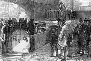
The inauguration of the London Pneumatic Despatch, showing the departure of the director's tour from the Holborn terminal (Source: Beach).
The pneumatic despatch was extended from Euston to Holborn. One source ([4]) suggests this line opened in 1862, although this seems unlikely given other evidence. Another source ([1]) suggests construction of the route did not start until September 1863, suggesting a route different from that shown in the company's prospectus (from Euston station, under Drummond Street, Hampstead Road and Tottenham Court Road to Broad Street, St Giles, where it turned sharply east under the company's offices at 245 Holborn). The first 'trains' ran on 10 October 1865, with a director's tour shortly after that date (shown in the accompanying picture). Capsules ran in tubes 4 feet 6 inches wide and 4 feet high. Power was initially provided by two horizontal engines with 24 in cylinders, three boilers, and a 22 ft diameter fan working at 150 rpm, creating air pressure and vacuum of about 5 oz/sq in [1]. Capsules achieved an average speed of 17 miles per hour. The initial system was reported to be under-powered, primarily because of excessive leakage of air.
A further route from Holborn to Gresham Street, and hence by branch 'line' to the Central Post Office on Cheapside was under construction at the time the Euston - Holborn route opened. A 3/8 mile tube from Holborn to Hatton Garden had been constructed by the time of the 1866 financial crisis [1]. £150,000 had been spent by this time. Construction was re-started in 1868, when unspecified additional finance was found for the route, and it was completed to Newgate Street (for the General Post Office) in 1869 [7]. The Newgate Street terminus was 1,658 yards from Holborn and 4,738 yards from Euston. The journey time from the General Post Office was 17 minutes, at speeds of up to 60 mph. The route included a section with two gradients of 1 in 15 to take the tubes across the Fleet Valley - a point at which water tended to fill the tube, resulting in certain consignments arriving at their destinations wet.
In 1860 the Post Office had been cautious about using the Pneumatic Despatch, stating "in the event of their scheme being successfully completed and brought into operation, the Post Office will be quite willing to consider the question of extending to the Mail Service any advantages which the Company's plans are capable of affording" [3]. The failure of the Post Office to use the system, combined with the loss of capital resulting from the 1866 financial crisis, caused the company serious financial problems.
The company obtained further powers to construct additional routes in London from Parliament in August 1872. One source ([1]) suggests routes were constructed to St Pancras, Kings Cross and Liverpool Street stations. Another source ([8]) suggest the company intended to build an extension to Pickford's parcel depot [in the city of London], which was not started due to a shortage of funds. The company opened the system to the public for the carriage of parcels, 'in the face of a Post Office monopoly' [8]. During 1872 the company stopped paying the Post Office rent for the station site at the General Post Office.
At the beginning of 1874 the Post Office respoded by agreeing to use the system for traffic from the Central Post Office to Euston. However it found only a 4 minute time saving to be achieved, and doubted the system's reliability or ability to convey heavier loads. In October 1874 the Post Office informed the company that there was no long term prospect of Post Office traffic on the system, and the system was shut [1]. The company gave notice of its liquidation in June 1875, although it was not wound-up until 7 March 1882 [8]. Rammell, like many others who have taken an interest in PCP, was said to be obsessed with the construction of such pneumatic 'railways' [7].
The tubes were retained for at least 20 years, while the Post Office considered electric traction. The company was restored in 1895, in the belief that the Post Office would wish to use the old tunnels. In 1899 the American, Batcheller acquired the rights of the Pneumatic Despatch Company, with a view to developing services for the Post Office. The tunnels were eventually purchased by the Post Office in 1921, to run telephone cables in [8]. In 1928 a build up of gas in one of the disused tunnels caused an explosion near High Holborn. The Post Office was forced to investigate and fill in or ventilate all similar tunnels. In 1930 four of the original vehicles were recovered north of Euston. At least two of the original vehicles still survive. One is displayed in the Museum of London. The other was initially displayed in the Bruce Castle Museum in Tottenham, London, before being moved to the British National Railway Museum at York. It is on public display behind an exhibit from London's underground Post Office railway - a very visual statement of the relationship between the two systems.
Whitehall Pneumatic Railway

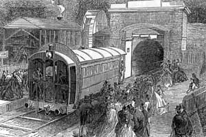
The Crystal Palace pneumatic railway demonstration (Source: Beach).
At the time of the opening of the first London Pneumatic Despatch Company scheme, Rammell suggests that the technology would be suitable for conveying passengers [9]. He envisaged groups of carriages "placed at distances coinciding with with the stations, and these carriages would be worked by the elastic rope of the air in a continuous circuit ... one set of carriages goin along one side of the double tube, and another returning by the other tube. It would be so aranged, however, that between station and station, only one group of carriages could by possibility be in the tube at the same time, thus preventing any possibility of accident either by collision or by one carriage overtaking another." A system for the carriage of passengers appears as a prototype during the Crystal Palace Exhibition of 1864. This 600 yard long, single tunnel and capsule system was a demonstration for the Whitehall Pneumatic Railway [8/10].
The [Waterloo and] Whitehall Pneumatic Railway was to have linked Waterloo and Charing Cross, a distance of less than a mile, under the River Thames [11]. This would have been only the second underwater crossing of the Thames. The existing bridges over the Thames at this point were toll bridges. The railway hoped to extract at least some revenue from these bridges. Once the first section was complete, it was intended to extend it from Charing Cross to Tottenham Court Road, and from Waterloo to the Elephant and Castle. This would have been a similar alignment to the later 'Charing Cross' branch of what is now the London Underground Northern Line, except that the Whitehall Pneumatic Railway was to have been relatively close to the surface. For example, the Charing Cross station proposed in Great Scotland Yard was to have been just 16 feet below the surface. Gradients of 1 in 30 were proposed.
A single tube would have been used, although three trains would have been operated, two loading and unloading, while the third was in transit. It was proposed to operate a service every 2 minutes, although such a high frequency would not have been practical using a single tube. Carriages (capsules) were to have been propelled through a brick-lined pipeline of diameter 18 feet. This would be done by using a single engine house at Waterloo, which propelled capsules by force of compressed air to Charing Cross, and vacuum back to Waterloo. The section under the Thames was made of iron and coated in concrete to give it the same specific gravity as the Thames river water. The pipeline section would then be laid on the river bed. Construction of the scheme began around 1865. By beginning of 1867 the first tunnel section had been completed by Messrs Samuda of Poplar, East London. The river bed had been dredged and piers of masionary constructed beneath the river bed to support the tube [12/13]. The scheme fell foul of the 1866 financial crisis, which resulted in the collapse of one of a bank which had backed the company. Construction ceased in 1868 [8].
Various other proposals existed, for example a system under the Mersey between Liverpool and Birkenhead, which was eventually opened as a conventional railway system.
Alfred Beach

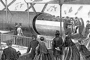
Alfred Beach's demonstration system, erected at the American Institute, Fourteenth Street, New York, 1867 (Source: Beach).
Alfred Beach proposed a number of systems in North America during the 1860s, including systems for the movement of passengers and mail [10]. His schemes were comparatively well documented by virtue of the fact that he was editor of the Scientific American during this period. Two pneumatic despatch systems were exhibited at the 1867 American Institute exhibition [14]. One was Beach's system for the movement of passengers. The demonstration system was a 107 foot long, 6 foot diameter pipe, in which a capsule containing 12 passengers plus conductor (Mr John D. Gilbert) was propelled. The system was powered by a 'Æolors' blowing wheel, itself powered by a small Root trunk engine. The Æolors wheel "is 10 feet diameter, made of wood, has eight blades, and revolves at the mouth of the tube opposite to that at which the car enters. When the screw turns in one direction it sucks the air through the tube and the car is drawn in" [14].
In 1867 Beach was elected president of the Pneumatic Dispatch Company of Jersey [14].
In 1869 the Beach Pneumatic Transit Company of New York constructed a 312 foot long system for the transport of passengers. It ran under Broadway from Warren Street to just beyond Murray Street, using a single tunnel of 9 foot diameter and was accessed via a station with a grand piano [1/15]. The system was reported to have only operated for a few months, and the company failed to get permission for further routes. Another source ([15]) suggests closure came in 1873 due to "political entanglement". The system tends to receive mention in most texts on the New York Subway. In 1912 contractors preparing to build the Broadway subway gained entry to the old tunnel and recovered one of the system's passenger cars, however no evidence of the station was recorded, leaving some to speculate as to what had happened to it [16].
Beach proposed a system for the movement of mail between on-street post boxes and post offices, in which letters posted into the post box dropped into a capsule waiting in a pipeline below the box [10]. In June 1869 the Govenor of New York approved an act to "facilitate the transmission of letters and merchandise by means of pneumatic dispatch" [17]. Initial proposals were to connect Brooklyn, Jersey City and all sub-post offices with the general post office, plus erect pneumatic letter boxes. Pneumatic letter boxes would allow letters and parcels to be collected and delivered by air pressure acting on capsules. A pilot line was due to be constructed late in 1869, between the post office at the corner of Nassau and Liberty Streets, and the City Hall Park. In 1870 a 1000 foot long 8 inch diameter test system was reported to have been constructed to serve a similar purpose, albeit without capsules [18]. Letters were dropped into the system and swept by suction to a large receiving box. The eventual outcome of this venture appears to be unknown.
Trans-American
In 1889, Mr W. Cross's Johnson Pneumatic Tube Company (of 135 and 137 Broadway, New York, USA) constructed an experimental 1,200 foot long, 30 inch diameter tube [19]. The system made use of rolling sphere carriers (capsules). The capsules were described as large cannonballs, 29 inches in diameter, made of iron, and weighing 750 pounds. The system was designed to convey goods (mail and 'valuable goods') over long distances, up to 150 miles. Capsules would travel at an average speed of 200 miles per hour. A capsule on the experimental system was reported to travel from one end of the 1,200 foot line, and back again in eleven seconds. On reaching the end of the line, capsules were slowed by an 'air cushion', a chamber 40 feet long, filled with compressed air. It was intended to construct long distance pipelines, using 'balls' weighing 500 pounds, with 400 horse power engines placed at intervals of 20 miles. Capsules would travel at an average speed of 200 miles per hour. Proposed future journey times between New York and Chicago of about five hours were predicted, and New York to San Francisco in 34 hours.
Notes
- An extract from a report on the first London Pneumatic Despatch Company scheme at Euston, by a journalist of the day [9]: "Within the modest brick shed near the bottom of Euston Square, there is the mouth of the tube, and there are the travelling trucks, ready to be thrust into it; and as we look, a bell rings at some distance up the rail - this is a signal that a mail-train has arrived at the Camden station, and that it will speedily be at Euston Square. At this signal we hear a shovel of coke thrown into a furnace, a small steam-enging begins to beat swiftly, and a whirring sound is heard within a great iron case which is noticed on the side of the shed. This, we are informed, is the pneumatic wheel - the mouth, in fact, which is to propel or draw the trucks through the tube. The wheel is twenty-one feet in diameter, and is composed of two discs of iron, not placed quite parallel to each other, but tapering off from the axis to periphery. These discs are braced together by spoke-like partitions, and these partitions communicate with an opening for the entrance of air about the axis. As this wheel rapidly revolves, the air is sucked in at its centre, and thrown off in a perfect gale at its open rim or edge. This gale is not allowed to disperse itself, however, but when any work has to be done, is confined within a paddle-box, and allowed to pass out at the will of the engineer through a pipe in connection with the great pneumatic despatch tube. In like manner, the air that is sucked in at the axle is all conducted from the despatch-tube by a similar pipe. Here, then, we have the means of pulling or pushing the travelling carriages along their subterranean road, and as we speak we see it in operation: for a mail-guard opens a door, throws in two or three mail-bags just snatched out of the guard's van as it rolls into the [mainline] station, the iron carriages are shoved into the tube, the air-tight door at its mouth is closed, and the engineer, with a turn of a lever, directs a torrent of air upon them, and we hear them rumbling off on their subterranean journey at a rate, we are informed, of twenty miles an hour. Ere we have done looking and wondering, we notice that a water gauge, on which the eye of the engineer has been fixed, becomes depressed at one arm and elevated at another. "It has arrived" he says; and almost ere he has said it, a bell connected with an electric telegraph warns him that the attendant at the other end of the tube is about to thrust the carriage into the tube on its return journey. It has been pushed along, as we have said, by the pressure of air thrown out by the wheel, but it has to be pulled back by suction; the value of the suction-pipe, in the connection with the centre of the disc, is accordingly opened, and speedily we hear a hollow rumbling, and out shoots the carriage, ready once more for fresh bags."
- Hadfield, Charles, (1967), Atmospheric Railways, David and Charles.
- Rammell, Thomas Webster, (1857), A new plan for Street Railways, London.
- Pneumatic Despatch Company (Limited), Prospectus, Undated (probably 1863), [cached text]
- Clayton, Francis Howard, (1966), The Atmospheric Railways.
- Simper, J., Baker, P., (1975), 'Pneumatic Pipeline Capsule Systems - The Future Potential', Pneumotransport 2, Guildford, BHRA, Cranfield.
- Vance, L., Mattson, P., (1994), Tube Transportation, US Dept of Transportation, Volpe National Transportation Systems Center, Feb, [summary cached text].
- Aldhous, P., Anderson, A., Coghlan, A., Mullins, J., O'Neill, B., Spinney, L., (1995), 'Beneath your Feet', New Scientist, 1st Apr, Vol.146, no.1972, pp5, ipc.
- Stanway, L., C., (2000), Mails under London, AEPS.
- Anon, (1863), The Living Age, Volume 77, Issue 984, April.
- Beach, A., (1868), The Pneumatic Dispatch, American News Co., Nassau St, New York.
- Anon, (1864), Scientific American, Volume 11, Issue 5, July.
- Anon, (1866), Scientific American, Vol. 15, Issue 23, Dec 1.
- Anon, (1867), Scientific American, Vol. 16, Issue 11, Mar 16.
- Anon, (1867), Scientific American, Vol. 17, Issue 16, Oct 19.
- Biederman, M., (1998), This Old Technology Hasn't Gone Down the Tubes, New York Times. Sunday, July 5, extract at http://www.deadmedia.org/ notes/36/369.html, [cached text].
- Brennan, J., (1998), Beach Pneumatic Transit, http://www.columbia.edu/~brennan/beach/, [cached text].
- Anon, (1869), Scientific American, Vol. 18, Issue 26, June 27.
- Howland, D., (undated), Pneumatic mail, Dead Media Working Note, http://www.deadmedia.org/ notes/34/346.html, and http://www.deadmedia.org/ notes/34/348.html, based on Scientific American, December 11, 1897, [cached text].
- Anon, (1889), Manfacturer and Builder, Volume 21, Issue 9, September.